Full Bridge and Center Tapped Designs Comparison
When designing a converter, the whole integrated solution must be taken into account. When choosing a topology for an application, magnetic components are, in general, the most critical part of the final design. Geometry, losses, and temperature distribution are directly affected by the chosen solution.
In this application note, how differences between a full-bridge rectifier and center-tapped rectification topologies affect the transformer design aspects is explained.
Basics
In certain DC-DC topologies, such as the half-bridge and full-bridge converters, two main full-wave rectification solutions can be implemented on the secondary side.
On the other hand, full-bridge rectification can be done with terminations for just one secondary winding. However, it needs four rectification diodes, as shown in the image below.
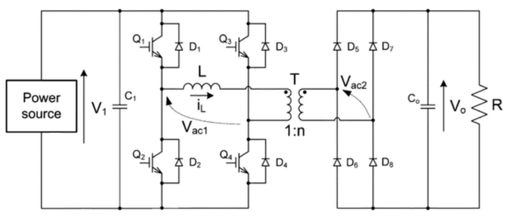
On the other hand, center-tapped rectification only makes use of two diodes (but with twice the peak inverse voltage). However, it needs three soldered termination points, which greatly increases the transformer manufacturing costs.
Design Example
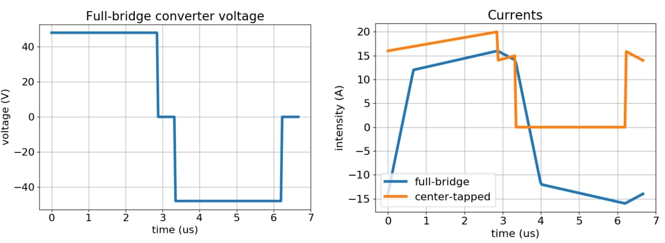
As the transistor bridge is the same in both topologies, the AC waveform generated at the primary side of the transformer is equal. For the design example, the circuit converts from 48 to 12 V.
The main difference is the maximum value of current that passes through the secondary. In the center-tapped case, the waveform in the other secondary is the same with a time displacement of T/2, and the peak is higher compared to the full-bridge rectifier. The RMS of the current applied with both topologies is 13A.
A design using Frenetic, with the waveforms above, is shown in the following section.
Results
The most important difference between both designs is the number of turns in each of the secondary. As the turns ratio of 4:1 is always necessary, the total number of turns is double in the center-tapped (considering each half as an individual winding).
Because of this, the optimized shape has a greater volume, and the transformer utilization factor is lower in the bridge rectifier.

As the current intensity waveforms are also different, winding losses also vary, being higher in the case of the center-tapped transformer, although not significantly in this example.
Conclusion
The rectification stage topology has a great influence on the transformer cost and performance. When deciding which circuit to use, the analysis of the magnetics is important, particularly if the available volume is limited.
In general, even though more diodes are needed, the preferred topology is the full-bridge rectifier. It yields less cost in the transformer manufacturing, less overall turns in the secondary, and less peak current. The decisive feature is the envelope volume. When it is a constrained design, with bridge rectification, the optimum volume can be greatly reduced.
Do you want the full version?
Login or Signup for our newsletter!
