Leakage Inductance in Transformers
Designing a magnetic component with a specific leakage inductance can be challenging and difficult to predict as the theoretical results commonly differ from reality.
The objective of this App Note is to show how to control the leakage inductance, and check the theoretical knowledge with experimental results.
Leakage Inductance
Leakage inductance is produced by the imperfect magnetic coupling between the transformer windings. The magnetic flux generated in the primary winding is never transferred 100% to the secondary winding. In cases where higher leakage inductance is required, a magnetic shunt can be inserted between layers. Another possibility would be the use of fractional turns.
This leakage inductance depends basically on:
- The winding geometry
- The core geometry
- Number of turns
Due to the fact that the winding geometry and arrangement have a high influence on the leakage inductance, it gets really complicated to calculate it analytically and get reliable results. However, if you know the effect these parameters have on the leakage, you will be able to control it.

How to Reduce it
- Decreasing the number of turns and layers
- Reducing the insulator layer thickness
- Using the interleaving arrangement
- Lowering the mean turn length
- Increasing the core window width
- Decreasing the core window height
The reduction of the leakage inductance is important in order to obtain better power efficiency, but it goes as the expense of other parameters. For example, reducing the number of turns will also produce higher core losses.
On the other hand, it is important to have in mind the relationship between leakage inductance and parasitic capacitance. Lower leakage inductances will lead to higher capacitances: C1= 1/w2 lk1
In cases where higher leakage inductance is required, a magnetic shunt can be inserted between layers. Another possibility would be the use of fractional turns.
Experimental Results
In this section, 4 experiments are carried out with the purpose of showing the effect of the different options mentioned above, to reduce the leakage inductance.
- Experiment 1: PQ26/25 transformer with a turns ratio of 2:1.
- Experiment 2: PQ26/25 transformer with a turns ratio of 2:1 but the number of turns is half than in experiment 1.
- Experiment 3: PQ26/25 transformer with a turns ratio of 2:1 and P-S-S-P arrangement.
- Experiment 4: PQ26/20 transformer with a turns ratio of 2:1 and a P-S-S-P arrangement.
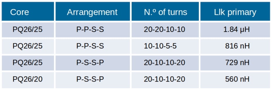
Results for experiments 1 and 2 show how the reduction of the number of turns will lead to a decrease in the leakage inductance. Comparing experiments 1 and 3 it can be appreciated how the leakage changes when the primary and secondary wires are alternated. Experiments 3 and 4 show the effect of the change in the height of the window; higher core windows will have higher leakage inductances.
Conclusions
Knowing the leakage inductance in advance can give you an idea of the total efficiency of the magnetic component before manufacture it. Theoretical calculations can give you an approach to the leakage inductance of a planar transformer, but when it is not planar, calculations become much harder and less accurate.
This is the reason why it is thought planar transformers have lower leakage inductance, but the fact is that it is because the interleaving arrangement in this type of transformers is easier to be carried out. Not only is important to predict it, but also to be able to control it. The experiment results show how the tips to reduce the leakage inductance are easy and effective.
Do you want the full version?
Login or Signup for our newsletter!
