Parasitic Capacitance in Planar Transformers
The use of planar transformers throughout the industry is growing fast due to their advantages as low profile, higher efficiency, manufacturing repeatability, and reduced electromagnetic interferences.
One of the characteristics of planar transformers is the possibility of obtaining a very good coupling between windings, but the drawback is the increment of the parasitic capacitance. Consequently, obtaining the value before manufacturing the transformer is crucial for avoiding potential problems.
Example of how Frenetic AI handles this Parasitic Capacitance
In this app note, we are going to prove the effectiveness of Frenetic AI calculating the parasitic capacitance comparing Frenetic estimation with the theoretically calculated using different models and real measurements. As an example, we will use a two layers PCB on the primary and two layers PCB on the secondary transformer.

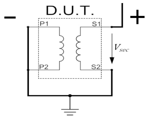
Laboratory measurements:
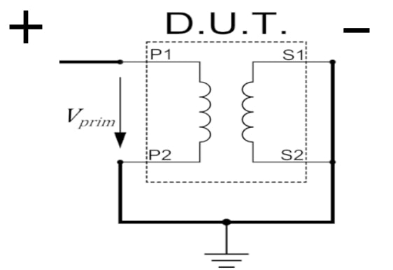
The values needed are obtained, with a measurement from the equipment Bode 100 and processing this data with the equations that follow.
Interwindig Capacitance:
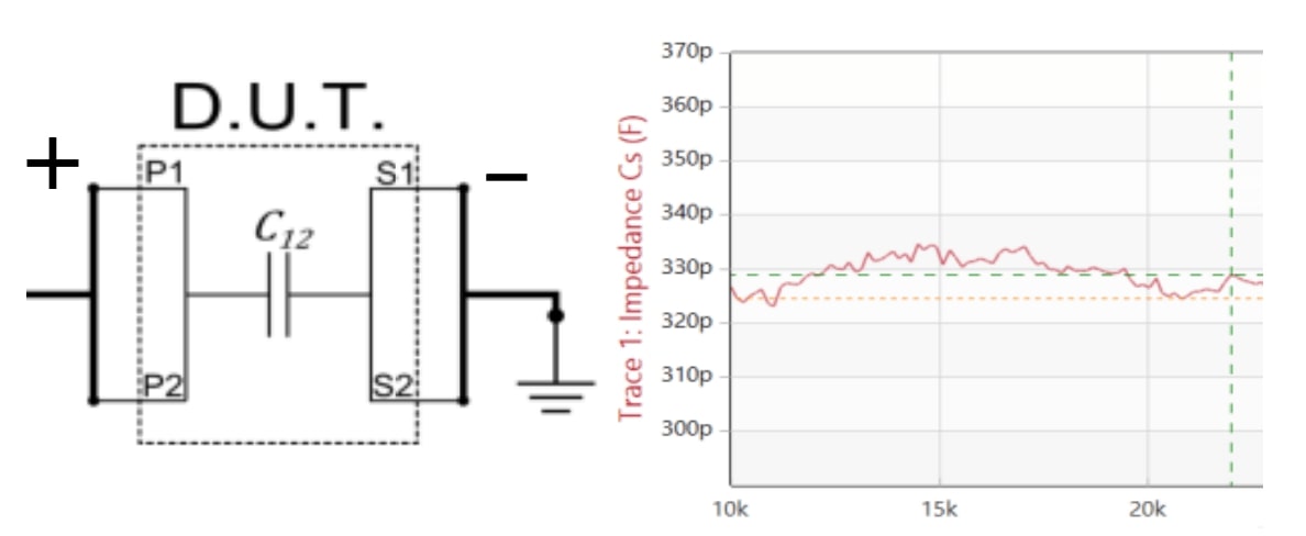
Primary Interwinding Capacitance:
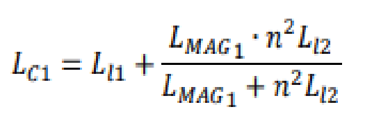

Where:
- LMAG: Magnetizing inductance
- Ll: Leakage inductance
- n: Number of turns
- ω: Angular frequency
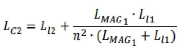
Secondary Interwinding Capacitance:
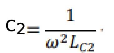
Classic models:
The theoretical models from (Ziwei Ouyang, Ole C.Thomsen, Majid Pahlevaninezhad, Djilali Hamza, Amish Servansing) are used for the theoretical estimation of the parasitic capacitance.
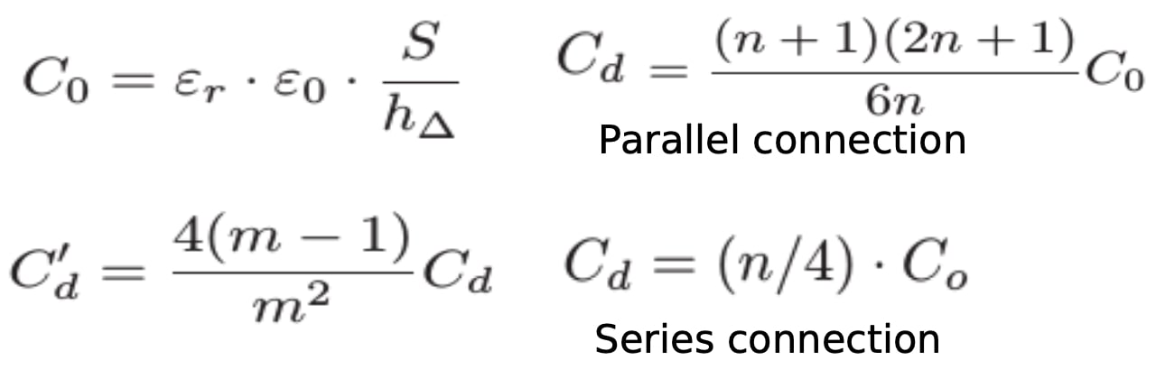
Where
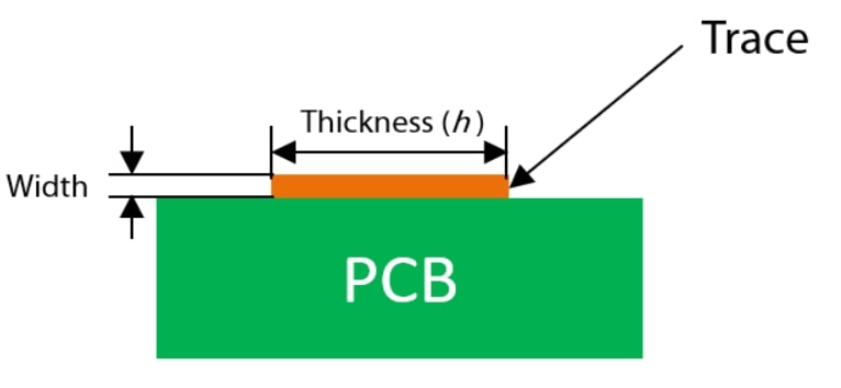
- S : overlapping surface area of the layers
- εo : permittivity of free air space
- εr : permittivity of the material
- hΔ : distances between the layers
- n : number of turns
- m : number of layers
- C0 : capacitance between two plates
- Cd : capacitance of the same winding
- C' d : capacitance in all layers
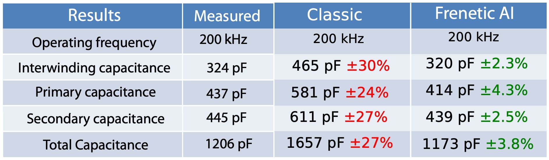
Solutions Obtained:
Case of study:
-Primary:(type A)
Turns = 8
Layers = 2
Thickness = 2oz
Area = 0.0064
-Secondary:(type B)
Turns = 1
Layers = 2
Thickness = 2oz
Area = 0.0064
Material = FR4
Frenetic AI found variables that were not considered in other models that affect the calculation of the capacitance and use them to obtain a solution really close to reality and also in a short time.
Conclusions
In planar technology, the PCB windings implementation causes higher parasitic capacitance than other technologies. The capacitance affects the resonance frequency and operation of the transformer, limiting the operating region of the transformer, therefore, obtaining a very accurate estimation will avoid future problems.
Do you want the full version?
Login or Signup for our newsletter!
