Winding resistance calculation in planar transformers
Nowadays, planar transformers are commonly used in the design of high-frequency power converters due to its advantages, like low profile, excellent thermal characteristics or power density. In the design of the transformer, an important step is the calculation of the winding losses, which depend on the winding AC and DC resistances.

WINDING DC RESISTANCE CALCULATION:
Where:
- ρ is the resistivity.
- l is the trace length.
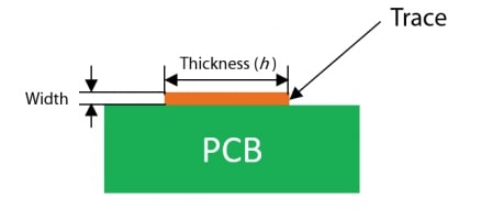
- A is the trace section: A = Thickness · Width
WINDING AC RESISTANCE CALCULATION:
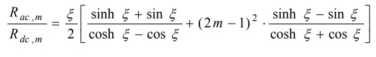
Where:
- ξ is the ratio of the layer thickness: ξ = h / δ
- h is the trace thickness.
- δ is the skin depth.
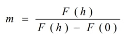
- m is the ratio of the proximity effect influence:
*This calculation gives an approximated AC resistance and does not consider the porosity factor and high-frequency effects related to the currents distribution that causes an extra winding loss.
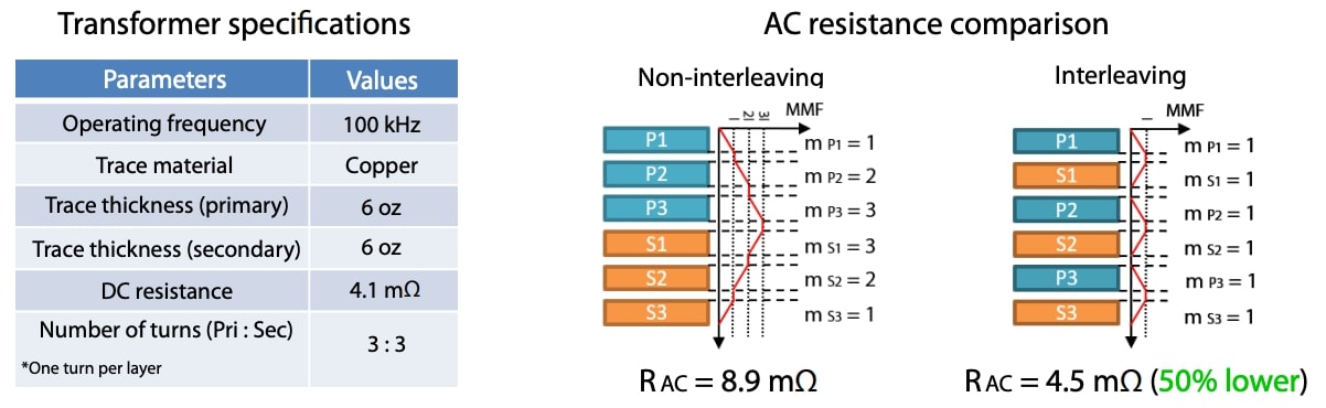
AC RESISTANCE CALCULATION USING AN INTERLEAVED AND NON-INTERLEAVED WINDING ARRANGEMENTS:
CONCLUSIONS
The winding AC and DC resistance calculation is a very important part of the magnetic design procedure for determining the total power losses. In order to obtain the optimum AC and DC resistances value, a lot of iterations are needed, covering, among other things, all the possible layers distributions or the trace thickness values in planar transformers. Frenetic, thanks to its AI technology, is able to determine the optimum design faster than classical methods.
Do you want the full version?
Login or Signup for our newsletter!
