Winding resistance key parameters
Key parameters to take into account when calculating winding resistances
One key aspect of the magnetic design process is the winding resistance calculation, that is the sum of the AC and DC resistances. Many variables have to be studied when the optimum magnetic element is required for a specified application, and the objective of this App Note is to introduce and compare the effect of the wire length, frequency and number of winding layers on the total resistance of Round AWG wires.
The spreadsheet used for creating these graphs is available via the following link:
https://drive.google.com/open?id=1FhbG8hJ1KQzEw8VdMqWCFtMPARuCoUFxtyEs-PTJ9AI
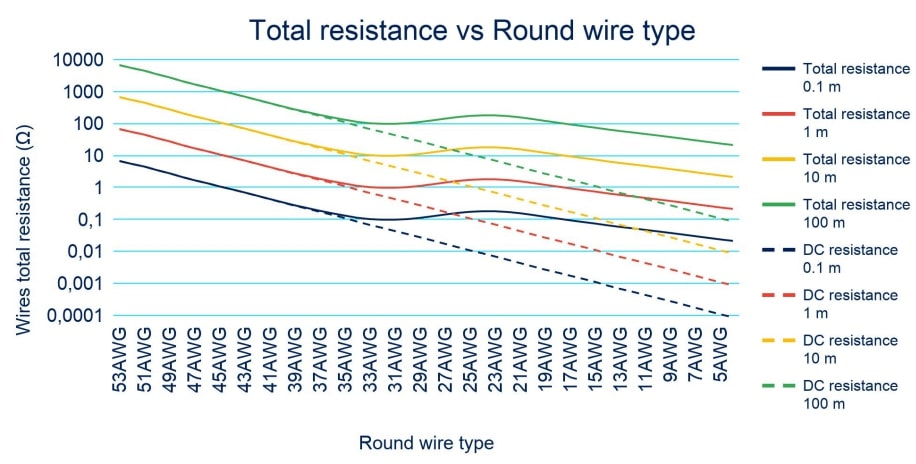
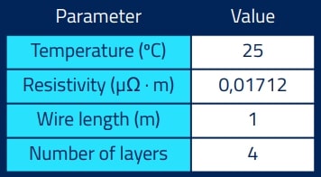
Total resistance vs length
A comparison between the wire resistances, with the wire length being the variable parameter, is presented in the graph to the right. An increase can be seen in the DC resistance when the wire length is greater, while the AC resistance effect on the total resistance maintains invariant.
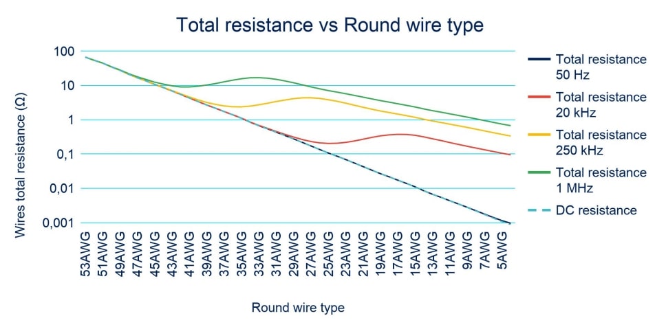
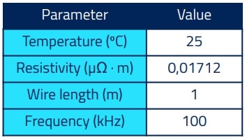
Total resistance vs frequency
This section shows how the frequency affects the total resistance, with higher AC resistance being observed when the frequency is higher. This effect is due to the skin effect depth being reduced, meaning a round wire with a lower diameter is optimal for the specified parameters.
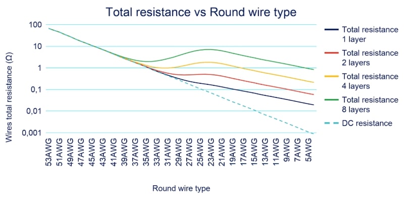
Total resistance vs number of layers
In this section, the graph shows how the total resistance increases due to the increase of the proximity effect with the number of layers in a winding without any interleaving. The result is that the optimum wire gauge is lower when the proximity effect increases.
Do you want the full version?
Login or Signup for our newsletter!
